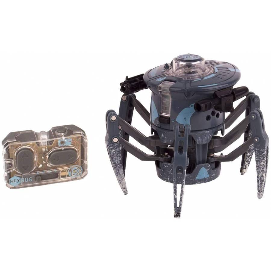


Or, I could combine it with some computer vision on my PC and have it chase my cat around. If I attached a pen to the Hex Bug, maybe I could make it walk around on a big piece of paper so that it would draw out a funny picture. If I cared to, I could no script a whole series of maneuvers. I can make it walk anywhere and shoot its gun on command. Testing it Out: As you can see in the video at the top of this post, this setup works pretty well for controlling the Hex Bug. Using the hacked remote so that I can use an Arduino to control my Hex Bug via So, as you can see below, I sneaked a black wire into that location and soldered it in place. After looking around the PCB, I decided that I liked the solder that was on the low side of the "fire" button. First, I connected a wire to the remote's ground. No extra components will be necessary!Ĭonnecting Ground: OK, we're mostly done talking. Electrically, this will mimic the behavior of the buttons themselves. When I want it to "press" a button for me, I'll command the relevant pin to go into a low-impedance state to allow it to conduct current to ground. Normally, I'll keep the Arduino's pins in a high-impedance state so that no current flows. This requires me to attach a wire to the high side of each button and to a attach a wire to the remote control's ground. My hacking approach, therefore, is to wire the Arduino to the remote control so that the Arduino can pull the lines low for me. When one of those lines goes from high to low, the microcontroller thinks that a button has been pressed. Hacking Approach: Based on this discussion, it is clear that the microcontroller on the remote control knows nothing about the only knows about the voltage being controlled by the buttons. As a result, the micro knows that the button was pressed. When the button is pressed, current flows through the button, which drops the voltage seen by the micro. When the button is not pressed, no current flows through it nor through the pull-up resistor, so the voltage seen by the micro is high. The microcontroller is continually sensing the voltage on the high side of the switch. The "high" side is connected to 3.3V via a pull-up resistor (probably inside the microcontroller). The "low" side of each button is tied to ground. When you press a button, the switch becomes closed-circuit. The buttons on this remote control are simply switches that are normally open-circuit.

How the Buttons Work: After a bit of probing of these test points, I learned that the buttons are used like most buttons in small devices like this (see "Button" demo by the Arduino folks for more info). With the arrows are for the user buttons. All those test points enable easy hacking.


 0 kommentar(er)
